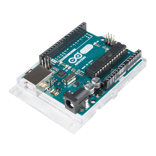
I recently decided to obtain an Arduino Uno R3, which, if we are to trust its online reputation, is supposed to be a promising platform for prototyping hardware development. The device came in a starter kit box with some other provided components such as resistors, a breadboard, a USB cable, LCD display, wires, LEDs, a tri-state 8-bit shift register, and a variety of sensors. It is fair to say that the kit promised a decent variety of components for a beginner to dive into Arduino hardware experimentation.
Having obtained the hardware, the next step was to set up a
development environment. The Arduino website provided
two options for my computer: I could use the Arduino IDE, or use the
Arduino command-line utility (arduino-cli). In theory,
everything that could be done in the official IDE could be done using
the command-line utility. I counterintuitively decided to try using the
command-line utility first. I was able to download it for macOS using
Homebrew (brew install arduino-cli). Then, I decided to use
VS Code to install the official Arduino
extension made by Microsoft.
The extension did not work with arduino-cli out the box.
It did not immediately detect the plugged in device (although it was
detected by running arduino-cli board list in the shell).
Several settings had to be set to allow the device to work:
"arduino.commandPath": "arduino-cli", "arduino.enableUSBDetection": true, "arduino.useArduinoCli": true, "arduino.path": "/opt/homebrew/bin/".
To make a project, the next step was to run
arduino-cli new BareMinimum in the shell, where
BareMinimum was my project title. This also works if you
manually make a folder and then make a file called
BareMinimum.ino within it. Within it you can put at a
minimum the following
code:
void setup() {
  // put your setup code here, to run once:

}

void loop() {
  // put your main code here, to run repeatedly:

}
After saving the code the next step was to ensure the interface with
the actual Uno device. First I could run
arduino-cli board list to identify the FQBN (fully
qualified board name) for my board. The next step was to search for
available ‘cores’ that would work with the board. The next step was to
run arduino-cli board listall uno. Following that I ran
arduino-cli core install arduino:avr. I could now compile
by running
arduino-cli compile --fqbn arduino:avr:uno BareMinimum and
then I could upload with
arduino-cli upload -p /dev/location --fqbn arduino:avr:uno BareMinimum
where /dev/location/ would be subsituted by the appropriate
/dev entry copied from the output of
arduino-cli board list.
After doing all this… the code was uploaded! Nothing of significance happened other than the light from the default LED remaining on. However, by creating another project it would be possible to observe a blinking effect.
void setup() {
    pinMode(LED_BUILTIN, OUTPUT);
}

void loop() {
    digitalWrite(LED_BUILTIN, HIGH);
    delay(1000);
    digitalWrite(LED_BUILTIN, LOW);
    delay(1000);
}
Later I was also able to use the VS Code extension and its board configuration settings to upload code from the IDE directly.
As you might notice from the example code, the Arduino language is a customized dialect of C++.
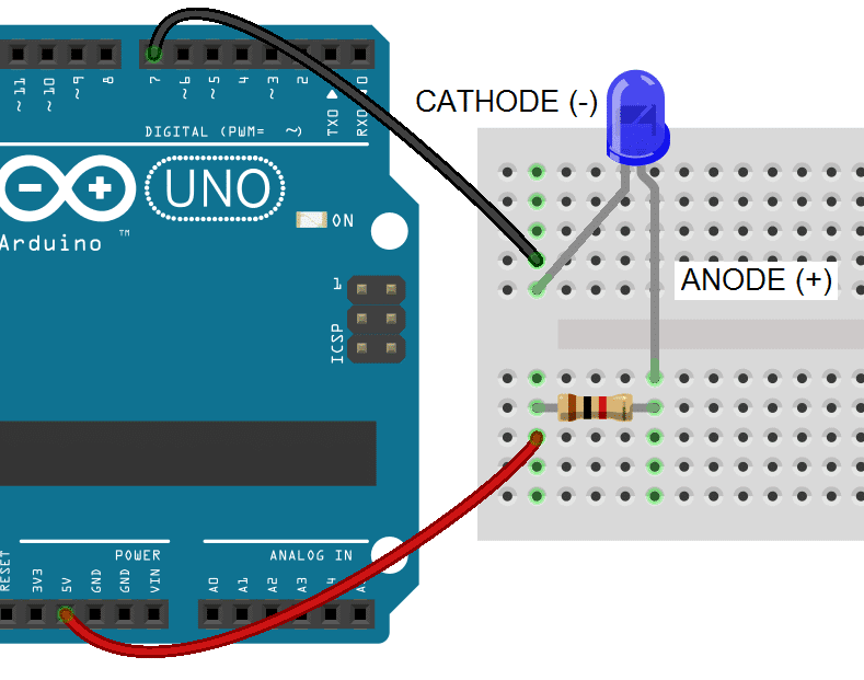
Following another guide it was possible to proceed to the next step. The next step was to try to use this board with some other hardware! I was able to use a basic LED:
void setup(){
    pinMode(7, OUTPUT);
    digitalWrite(7, LOW);
}

void loop(){
}
This was wired as follows (refer to the original link for more details), using a 1K Ω resistor:
I also found it helpful to check resistor values using an online resistor calculator. Resistance values in ohms are typically indicated by colored bands which correspond to certain values. It is important to note which side you begin reading the bands from, since you could obtain different values. An online source suggested reading from the side with grouped bands (never from the side with a metallic band). The resistor here plays the role of limiting current (as we know from the elementary formulation of Ohm’s Law, I = V/R) and therefore a higher resistance could be used to limit further the intensity/brightness of the LED. It is important to use resistors in electronics to protect against excessive current from damaging more sensitive components.
Another interesting feature of this simple circuit is to note that the LEDs used (any LEDs in fact) exhibit a characteristic polarity, that is, current can only flow in one direction and thus the LED must be wired accordingly. LEDs, or light-emitting diodes, like other diodes operate due to a p-n junction which is possible due to the use of semiconductors and impurities which ‘bias’ the current to only flow, for the most part, in one direction. As can be noted on the above image, the 5 volts are on the side of the the anode (+) side of the LED, also wired in series with the resistor. The cathode (-) side is connected to pin 7, which has a ‘LOW OUTPUT’ set by our code, which in according to the code documentation actually sets the pin to 0 volts. In theory, our setup would be similar to doing this:
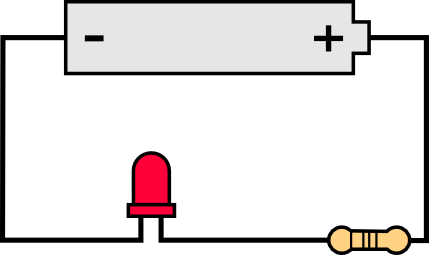
Or, if we were to follow the standard circuitry schematic, it would be similar to this (albeit with different numerical values for voltage and resistance etc):
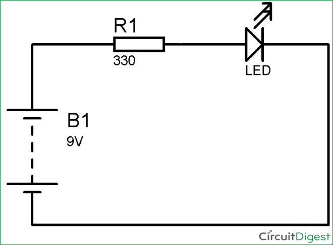
Nominally/conventionally, ‘current’ flows from positive to negative, that is, from our anode side to our cathode side (in actuality it is more like the electrons ‘flow’ from the negative to the positive side). Our current works out to be a little less than 5V/1000Ω = 5mA (unknown resistance of the LED itself).
It is also important to note the way that breadboards are wired. Supposedly, breadboards are named as such due to the historic usage of actual bread cutting boards for prototyping circuits. The wiring pattern of breadboards follows this pattern, where each slot within a rows is connected to the others in the row (not going through the middle however), as are each slot in a side column:

This was just a very elementary demonstration of how circuitry could be incorporated with hardware and software, and our humble ATMega328P microcontroller is sufficient to work with this circuitry!
Note: the code snippets in this page come from the linked pages, please refer to linked pages for source information and images as well as further details.